Below figure shows hierarchical organization of the H.264/AVC syntax. The Network Abstraction Layer (NAL) consists of a series of NAL Units. Sequence Parameter Sets (SPS) and Picture Parameter Sets (PPS) are NAL units that signal certain common control parameters to the decoder. Coded video data is communicated in Video Coding Layer (VCL) NAL units, known as coded slices.
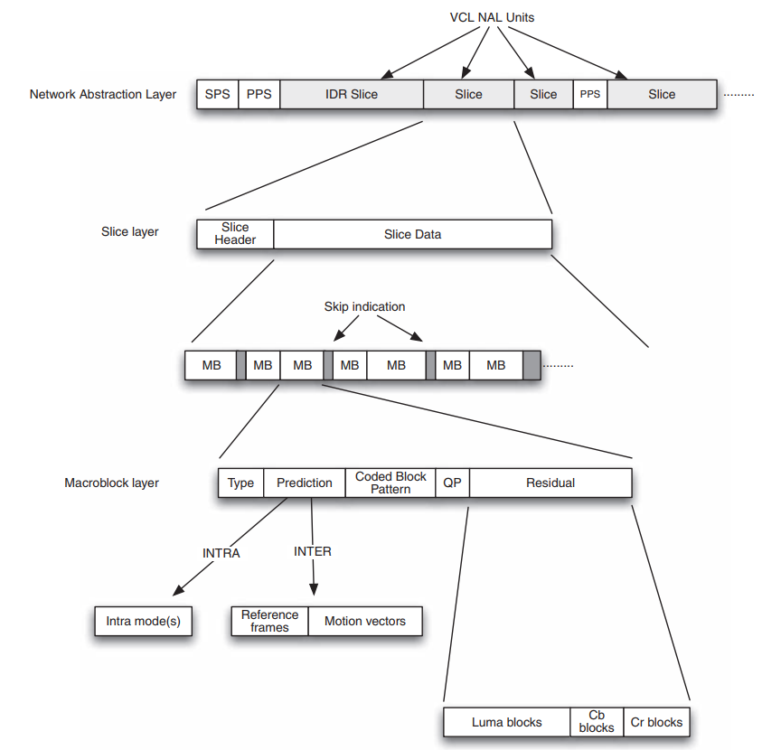
An access unit, a coded frame or field, is made up of one or more slices. Each slice consists of a Slice Header and Slice Data. The Slice Data is a series of coded macroblocks (MB) and skip macroblock indicators which signal that certain macroblock positions contain no data. Each coded macroblock contains the following syntax elements:
- MB Type : I/intra coded, P/inter coded from one reference frame, B/inter coded from one or two reference frames.
- Prediction information : prediction mode(s) for an I macroblock, choice of reference frame(s) and motion vectors for a P or B macroblock.
- Coded Block Pattern (CBP) indicates which luma and chroma blocks contain non-zero residual coefficients.
- Quantization Parameter (QP), for macroblocks with CBP not equal to 0.
- Residual data, for blocks containing non-zero residual coefficients.
A NAL unit contains a Raw Byte Sequence Payload (RBSP), a sequence of bytes containing syntax elements. H.264 syntax elements are binary codes with varying length and so a sequence of syntax elements within a NAL unit will not necessarily fit into an integral number of bytes. Zero-valued bits are added to the end of the RBSP contents in order to ensure that the length is an integral number of bytes.
Instantaneous Decoder Refresh
As shown in above image, A coded video sequence begins with an Instantaneous Decoder Refresh (IDR) Access Unit, made up of one or more IDR slices, a special type of Intra coded slice. Subsequent video frames or fields, described as Access Units, are coded as slices. The video sequence ends when a new IDR slice is received, signalling a new coded sequence, or when the transmission is complete.
Frames, fields and pictures
An H.264 encoder converts video frames into compressed or coded pictures. H.264/AVC defines a frame as an array of luma samples and two corresponding arrays of chroma samples. The two fields, top field and bottom field, that make up a frame may be sampled at the same time instant (progressive scan) or at different time instants (interlaced scan). The term picture refers collectively to a frame or a field. Frames or fields are encoded to form coded pictures, each of which is composed of one or more slices. Slices are decoded to produce decoded pictures which are stored in a Decoded Picture Buffer (DPB). Pictures in the DPB may be used for inter prediction of further coded pictures and/or output for display. It is important to distinguish between three different orders of pictures:
- Decoding order, the order in which pictures are decoded from the bitstream
- Display order, the order in which pictures are output for display
- Reference order, the order in which pictures are arranged for inter prediction of other pictures.
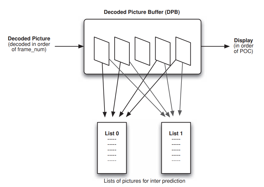
As shown in above figure, the decoding order of pictures is indicated by the parameter frame_num. The display order of pictures is determined by the parameters TopFieldOrderCount and BottomFieldOrderCount, collectively described as Picture Order Count, POC. The reference order of pictures is determined by one or two lists, each of which is an ordered list of all the available decoded pictures. A P slice uses a single list, list0, and a B slice uses two lists, list0 and list1. A list contains available reference pictures in different orders.
Orders in H.264
- Decoding order, the order in which pictures are decoded from the bitstream. The parameter frame_num, decoded from the slice header, determines the decoding order of coded frames or fields. Except in certain special cases, frame_num for each decoded picture increases by one compared with the previous reference frame in decoding order.
- Display order is determined by the POC parameters TopFieldOrderCount and BottomFieldOrderCount which are derived from the slice header using one of three methods:
- Type 0: The least significant bits of POC are sent in every slice header. This allows maximum flexibility but typically requires more bits than the other methods.
- Type 1: A ‘cycle’ of POC increments is set up in the sequence parameter set and POC changes according to this cycle unless otherwise signalled in the slice header using a Delta offset. The cycle defines the interval between frames used for reference, plus a POC offset to frames not used for reference.
- Type 2: POC is derived directly from frame_num and display order is the same as decoding order.
A P slice uses a single list of reference pictures, list0 and a B slice uses two lists, list0 and list1. In each list, short term reference pictures are listed first followed by long term reference pictures, in increasing order of LongTermPicNum. The default short term reference picture order depends on decoding order when the current slice is a P slice and on display order when the current slice is a B slice. The list orders are important, since indices to reference pictures earlier in the list require fewer bits to signal. Hence the default orders are organized so that reference pictures temporally ‘nearer’ to the current picture occur earlier in the list, since these are likely to contain the best prediction match for the current picture.